


Download Tempo Drainage Design Guide
Basic drainage design is relatively simple by following this easy 10-step process.
Before we start there are 4 important points to remember:
- Excess water always collects at the lowest elevation points.
- Design for worst case conditions and not for average conditions.
- Although obvious, water can only flow downhill.
- Be generous in the design-if in doubt add an extra collection point (grate) and rather oversize than undersize a component.
In order to help understand the basic steps of designing a drainage system, consider the following example:
A contractor needs to install a drainage system in the backyard of a house in Atlanta, Georgia. The backyard is comprised of 3 areas, a loamy soil flower bed, a grass area and a concrete deck. The flower bed area is 6’ wide x 20’ long (area of 120 sq ft), the grass area is 20’ wide x 24’ long (area of 480 sq ft) and the concrete deck area is 40’ wide x 20’ long (area of 800 sq ft). The distance from the backyard to the street is 100′.
STEP 1:
Determine the Rainfall Intensity of the property.
Different parts of the country have varying rainfall intensity profiles. Use Table 1.1 below to determine the Rainfall Intensity (I) of the property. Keep in mind that the table below has been simplified (more sophisticated data is available on the web that contain 100 year one-hour rainfall maps, etc.)
Table 1.1
| Rainfall Intensity Zone | States in the USA | Rainfall Intensity |
| Zone A | AL, FL, GA, HI, LA, MS, NC, OK, SC, TN, TX | 5.0 inches per hour |
| Zone B | AR, CT, DE, DC, IA, IL, IN, KS, KY, MA, MD, MI, MN,MO, ND, NE, NH, NJ, NY, OH, PA, RI, SD, VA, WV, WI | 3.5 inches per hour |
| Zone C | AK, AZ, CA, CO, ID, ME, MT, NV, NM, OR, UT, VT, WA, WY | 2.0 inches per hour |
As the property in our example is in Atlanta, GA, it falls into Rainfall Intensity Zone A with a Rainfall Intensity of 5.0 inches per hour.
STEP 2:
Calculate the maximum run-off potential flow for each area.
In order to correctly size the drainage pipe network, the maximum run-off flow for each area must be calculated. A frequently used formula for calculating the maximum runoff potential from a small area (under 200 acres) is the Rational Method. The Rational Method Formula is:
![]() where:
where:
Q = peak runoff flow (gallons per minute)
C = coefficient of runoff
I = rainfall intensity (inches per hour)
A = drainage area (square feet)
For our example, we already know the area (A) of each zone to be drained. The flowerbed is 120 sq feet, the grass area is 480 sq feet and the concrete deck area is 800 sq feet.
Next, we will determine the coefficient of runoff (C) for the surface type of each area to be drained using Table 2.1 below. The coefficient of runoff for the loamy soil flowerbed is 0.45, for the grass area is 0.35 and for the concrete deck area is 0.90.
Table 2.1
| Surface Type | Coefficient of Runoff |
| Concrete or Asphalt | 0.90 |
| Clay | 0.60 |
| Gravel | 0.50 |
| Loam | 0.45 |
| Sand | 0.40 |
| Grass | 0.35 |
Lastly, we will use the Rational Formula to calculate the peak runoff flows for each area.
For the flowerbed: Q = (0.45 x 5.0 x 120) / 96 = 2.8 gallons per minute
For the grass: Q = (0.35 x 5.0 x 480) / 96 = 8.8 gallons per minute
For the concrete deck: Q = (0.90 x 5.0 x 800) / 96 = 37.5 gallons per minute
Adding these together, the total combined area maximum runoff flow (Q) is 49.1 gallons per minute.
STEP 3:
Choose the number of drainage zones.
When designing a drainage system, attention must be paid not to exceed the maximum flow capacities of the drainage pipe (as show in Table 3.1 below). Using either 3″, 4″ or 6″ drainage pipe is recommended on most residential and light commercial projects as these pipe sizes and applicable fittings are readily available and easy to install.
Table 3.1
| Pipe Size | Maximum Flow Capacity |
| 3″ | 44.0 GPM |
| 4″ | 75.0 GPM |
| 6″ | 175.0 GPM |
In our example and using Table 3.1 above, there are two choices to accommodate the maximum property run-off flow calculated in step 2 of 49.1 GPM.
- A single 4″ or larger pipe may be used (a single Drainage Zone system).
- Two separate 3″ or larger pipes with two discharge points could be used (a two Zone Drainage system).
For the example we are using, as 3” pipe is easier to install and cheaper than 4” or 6” pipe, we will select a two Drainage Zone system using 3” pipe with two independent discharge points. However, if 4” or 6” pipe is more readily available than 3” pipe, you may choose to use that instead.
Drainage Zone 1 will comprise the flowerbed area and the grass area (maximum run-off flow for that combined area is 11.6 GPM) and Drainage Zone 2 (maximum run-off flow is 37.5 GPM) will comprise the concrete deck area.
STEP 4:
Locate the basin and/or grate positions.
Locate the low spots on the property where excess water could accumulate. Once these are finalized, they become the basin and/or grate locations. In the example above, let us assume that each of the 3 areas described has a single low point within its confines. The first basin and/or grate is located in the flowerbed, the second basin and/or grate is in the grass area and the third basin and/or grate is in the concrete deck. If there is more than one low point within an area, each of these would be a collection point and a location for a basin and/or grate.
STEP 5:
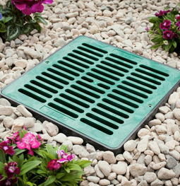
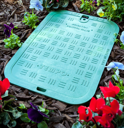
Decide whether a flat or atrium (domed) grate is appropriate.
Flat grates are typically used in areas where there is pedestrian, wheelchair, or light duty auto traffic. Atrium grates are domed and typically used where there is no pedestrian traffic and where mulching, leaves, or other debris could be present that could plug the flat grate.
In the previous example problem, assume that the flowerbed has been mulched and leaves may also be present. Therefore an atrium grate (Grate 1) is recommended. For the grass area, a flat grate (Grate 2) must be used as there will be lawnmower and foot traffic present. For the concrete deck area, a flat grate (Grate 3) must also be used.
STEP 6:
Select the appropriate grate size for each area.
Using the maximum runoff flows from each area that we calculated in Step 2, divide each area’s flow by the number of grates locations in that area to calculate how much flow each grate needs to handle. Once you have calculated each grate’s flow requirements, use Table 6.1 below to select the grates.
Table 6.1
|
|
|
In the example, for the flowerbed area (with only one grate location) and a maximum runoff flow of 2.8 GPM, we choose a 3” atrium grate, which has a maximum flow rate of 12 GPM. For the grass area (with only one grate location) and a maximum runoff flow of 8.8 GPM, we choose a 6” round flat grate which has a maximum flow rate of 16 GPM. For the concrete deck area (with only one grate location) and a maximum runoff flow of 37.5 GPM, we choose a 9” flat grate which has a maximum flow rate of 50 GPM.
As we previously decided to use all 3” drainage piping, check on Table 6.2 below that all of the grate sizes chosen can be used with 3” pipe.
Table 6.2
| Grate Size | Pipe Diameter Options |
| 3″ | 3″ pipe connecting directly on to grate |
| 3″ Brass | 2″ Schedule 40 or 3″ pipe1 |
| 4″ | 4″ pipe connecting directly on to grate |
| 4″ Brass | 3″ or 4″ pipe2 |
| 6″ | 6” pipe and 3” or 4” pipe when used with 6” catch basin |
| 6″ Universal | 3” or 4” pipe when used with or without 6” catch basin |
| 9″ | 3”, 4” or 6” pipe when used with 9” catch basin |
| 12″ | 3”, 4” or 6” pipe when used with 12” catch basin |
| 18″ | 3”, 4” or 6” pipe when used with 18” catch basin |
- Fits 2” Schedule 40 pipe attaching directly to PVC collar or fits 3” pipe via 3” S&D fitting.
- Fits 3” pipe attaching directly to PVC collar or fits 4” pipe via 4” S&D fitting.
There are no catch basins available for 3” or 4” grates as they connect directly to drainage pipe. When using the 9”, 12” and 18” grates a catch basin or low profile basin must be used. The only time a decision needs to be made is when using a 6” round or 6” square grate. In our example, a catch basin must be used for the 6” grate because we are connecting it to a 3” pipe.
In our example, all three can indeed be used with 3” pipe. The 3” grate will connect directly to 3” pipe, the 6” grate will connect to the 3” pipe using a 6” catch basin and the 9” grate will connect to 3” pipe using a 9” catch basin.
However, if say the flowerbed area had been 600 sq ft instead of 120 sq ft, the Rational Method formula in Step 2 would have increased the maximum runoff flow from 2.8 GPM to 14.1 GPM. The 3” atrium grate that you had previously chosen would not have been adequate and a 4” atrium grate would be required. In this case, you would need to use 4” pipe for the drainage system. If you still preferred to use 3” pipe, then a suggestion would be to use two adjacent 3” atrium grates (each grate would then handle just over 7.0 GPM which is within its maximum capacity of 12 GPM).
Note: There are three common types of drainage pipe and fittings that are used. Tempo’s grates are designed to be used with all of them. Please refer to the Appendix at the end of this guide for more information on the different types of drainage pipes and the appropriate fittings.
STEP 7:
Select the grate colors.
The most commonly used grate color for grass areas is green. When used with concrete applications, grey grates may be the most appropriate color. In other areas however, grate colors are more a matter of personal preference. In Table 7.1 below, you can see the different color options available.
Table 7.1
| Grate Description | Available Colors |
| 3″ Round Flat Grate | Green / Black / Sand / Grey / Purple |
| 3″ Round Atrium Grate | Green / Black / Sand |
| 3″ Round Flat Grate and PVC Collar | Brass |
| 4″ Round Flat Grate | Green / Black / Sand / Grey |
| 4″ Round Atrium Grate | Green / Black / Sand |
| 4″ Round Flat Grate and PVC Collar | Brass |
| 6″ Round Flat Grate | Green / Black / Sand / Grey |
| 6″ Round Atrium Grate | Green / Black / Sand |
| 6″ Square Flat Universal Grate | Green / Black / Sand / Grey |
| 9″ Square Flat Grate | Green / Black / Sand / Grey |
| 9″ Square Atrium Grate | Green / Black |
| 12″ Square Flat Grate | Green / Black / Sand / Grey |
| 12″ Square Atrium Grate | Green / Black |
| 18″ Square Flat Grate | Green / Black / Sand / Grey |
STEP 8:
Decide where to re-route this water.
There are many options for re-routing the water that is collected in the grates and piping. Some of the most common applications for re-routing the water are to the street curb, to a storm water drain, to another landscaped area that can safely handle large volumes of water, to a French drain or to a storage tank that would allow for irrigation at a later time.
Let us assume that for this project, the run-off water will be re-routed to the street curb. Remember that the water must flow only downhill (even a small uphill section will prevent your system from draining properly). As the distance that the run-off water needs to travel is 100 ft, the recommended elevation drop from any grate to the discharge point must be a minimum of 2’ or 24”. (Minimum recommended slope should be 24” per 100 ft or approximately 1/4” per foot). For optimum results this slope should be fairly uniform.
If the natural topography of the area to be drained does not have the necessary fall to meet the minimum slope requirements, you will need to dig a trench with the minimum slope required and then use a combination of low profile basins and catch basins, some of which will have one or multiple risers to make sure that grates end up at grade level.
STEP 9:
Design piping network.
There are 2 options for the 3” piping network for the grass and flowerbed areas. These grates can either be plumbed inline or have two separate 3” drainage pipes that are later connected into a single 3” discharge pipe.
The plumbing for the drainage pipe from the concrete deck area will be a single 3” pipe that runs from the 9” basin to the discharge point.
STEP 10:
Choose the discharge end device.
In our example, the ends of the drainage pipes will be cut flush with the street curb so no additional parts are needed. However, in many cases the drainage pipe terminates on the property and it is best to close it off with a grate or a pop-up relief valve to prevent debris or rodents from entering. This pop-up relief valve sits flush with the surrounding area and only pops up to allow excess water to discharge when the drainage pipe is full.
APPENDIX
Drainage Pipe
There are three common types of drainage pipe to use.
- Corrugated Pipe is flexible and typically can make directional changes without the need for fittings. The advantages of this type of pipe are its flexibility and its ease of installation. The disadvantages are that it is hard to clean out (because of the corrugations), the connections are not very watertight and that the trench bed has to be very carefully sloped.
- Sewer and Drain Pipe is a thin walled PVC pipe. This pipe needs Sewer and Drain hub fittings to make directional changes and joins. Because of its smooth wall, it is easier to clean and the trench bed slope and smoothness is less critical as this pipe will somewhat compensate for peaks and valleys.
- Triple Wall Pipe is similar to the above but has a heavier wall and is thus sturdier. It also requires Sewer and Drain hub fittings to make directional changes. Because of its rigidity, the trench bed slope and smoothness is even less critical than with the Sewer and Drain pipe described above.
Fittings
There are 2 common types of fittings that can be used.
- Sewer and Drain PVC hub fittings are used to couple the drainage pipe and change directions. The most popular and readily available 3″ and 4″ fittings are straight couplers, 90 degree, 45 degree and 22.5 degree elbows, straight and sanitary tees, 45 degree wyes and end caps. These fittings are solvent welded onto the pipe.
- Single Wall corrugated fittings are used to couple the drainage pipe and change directions. The most popular and readily available fittings are straight couplers, 90 degree elbows, 45 degree wyes, tees and end caps. These fittings snap directly onto the drainage pipe.